
6.9 KiB
DDS
SKU:U105


Description
DDS is a signal source Unit. It uses the AD9833 programmable waveform generator + STM32F0 micro controller. Based on I2C communication interface (addr:0x31) It can easily control the signal source to output multiple waveforms (sine wave, triangle wave, square wave output, sawtooth wave, signal output amplitude 0-0.6V) and adjust the frequency and phase.
It supports deep sleep mode, which can reduce the power consumption in the idle state. The Unit is suitable for the electronic circuit prototype design of various test instruments as a signal source.
Product Features
- Digital programmable frequency and phase
- Signal output amplitude 0-0.6V
- Sine wave/Triangle wave/Square wave/Sawtooth wave (fixed frequency: 13.6KHz)/DC output
- Output frequency range: 0MHz to 1MHz (10MHz based on the reference clock)
- 28bit frequency resolution
- 11bit phase resolution
Includes
- 1x DDS Unit
- 1x HY2.0-4P cable
- 1x SMA-2.54mm cable
Application
- Frequency stimulation/waveform generation
- Liquid flow and airflow measurement
- Sensor applications: proximity, motion and defect detection
- Line loss/attenuation
- Testing and medical equipment
- Scan/clock generator
- Time domain reflectometry (TDR) application
Specification
| Specifications | Parameters |
| Support waveform | Sine wave/Triangle wave/Square wave/Sawtooth wave (fixed frequency: 13.6KHz)/DC output |
| Signal output amplitude | 0-0.6V |
| Output frequency range | 0MHz to 1MHz (10MHz based on the reference clock) |
| Frequency resolution | 28bit |
| Phase resolution | 11bit |
| Net weight | 11.1g |
| Gross weight | 34.7g |
| Product size | 71*24*8mm |
| Package size | 88.5*60*21mm |
Related Links
EasyLoader
EasyLoader is a concise and fast program writer, which has a built-in case program related to the product. It can be burned to the main control by simple steps to perform a series of function verification. Please install the corresponding driver according to the device type. M5Core host Please click here to view the CP210X driver installation tutorial
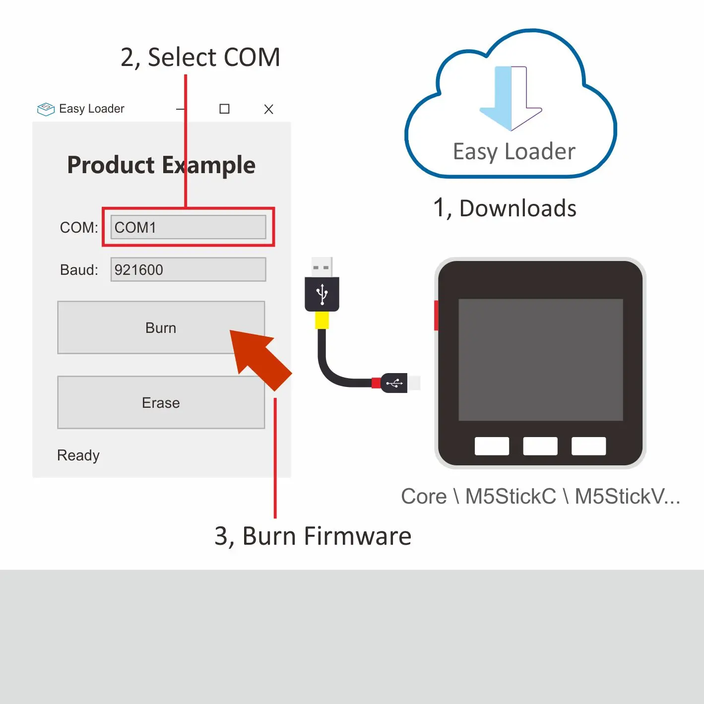
Description:
Control DDS Unit Output Sine wave/Triangle wave/Square wave/Sawtooth wave.
Example
1. Arduino
Schematic

Pin mapping
| M5Core | SCL | SDA | 5V | GND |
| DDS Unit | GPIO22 | GPIO21 | 5V | GND |
Protocol
- Protocol type I2C
- I2C Address: 0x31
When writing a register, the highest bit must be set to 1. The mclk is set to "1" by default, it will keep the last output signal magnitude. Once the DAC is set to 1, it stops the Unit output.
/*--------------------------------------------------------------------------------------------------*/
 | DDS CTRL REG       | 0x20
 | ------------------------------------------------------------------------------------------------
 | dds_ctrl_reg[0]  |  R/W  | System control
                            | 7 | 6 | 5 | 4 | 3 | 2 | 1 | 0 |
                            | W | R | R | R | R |    MODE   |

                            | -MODE: 000 Reserved
                            |        001 SINE
                            |        010 TRIANGLE
                            |        011 SQUARE
                            |        100 SAWTOOTH
                            |        101 DC
//
 | dds_ctrl_reg[1]  |  R/W  | System control
                            | 7 | 6       | 5       |  4  |  3  |  2   | 1 | 0 |
                            | W | FSELECT | PSELECT | S01 | S12 | RSET | R | R |

                            | -FSELECT: 0 Used FREQ0
                                        1 Used FREQ1
                            | -PSELECT: 0 Used PHASE0
                                        1 Used PHASE1
                            | -SLEEP01: 1 Disenable mclk
                            | -SLEEP12: 1 Disenable DAC
/*----------------------------------------------------------------------------------------------------

/*--------------------------------------------------------------------------------------------------*/
 | DDS FREQ PHASE REG       | 0x30
 | ------------------------------------------------------------------------------------------------
     | dds_freq_phase_reg[0:3]  |  R/W  | FREQ(28bit)
                                        | 31 | 30 | 29:28 | 27:0       |
                                        | W  | N  |   R   | freq reg 0 |
    //
     | dds_freq_phase_reg[4:5]  |  R/W  | PHASE(12bit)
                                        | 15 | 14 | 13:12 | 11:0        |
                                        | W  | N  |   R   | phase reg 1 |
//
/*---------------------------------------------------------------------------------------------------*/