
14 KiB
M5Core2
SKU:K010


Tutorial&Quick-Start
Choose the development platform you want to use, view the corresponding tutorial&quick-Start.
Description
M5Core2 is the second generation core device in the M5Stack development kit series, which further enhances the functions of the original generation of cores.
The MCU is an ESP32 model D0WDQ6-V3 and has dual core Xtensa® 32-bit 240Mhz LX6 processors that can be controlled separately. WiFi and Bluetooth are supported as standard and it includes an on board 16MB Flash and 8MB PSRAM, USB TYPE-C interface for charging, downloading of programs and serial communication, a 2.0-inch integrated capacitive touch screen, and a built-in vibration motor.
M5Core2 also features a built-in RTC module which can provide accurate timing. The power supply is managed by an AXP192 power management chip, which can effectively control the power consumption of the base and a built-in green LED power indicator helps to notify the user of battery level. The battery capacity has been upgraded to 390mAh, which can power the core for much longer than the previous model.
The M5Core2 retains the TF-card(microSD) slot and speakers. However, in order to ensure higher quality sound output, the I2S digital audio interface power amplifier chip is used to effectively prevent signal distortion. There are independent power and reset buttons on the left side and bottom of the base.
The 3 icons on the front of the screen are capacitive buttons which are programmable. There is a small expansion board on the back of the base with a 6-axis IMU sensor and microphone. The development platform and programming language supported by M5Stack Core2: Arduino, UIFlow (using Blockly, MicroPython language) No matter what level of your development and programming skills, M5Stack will help You gradually turn your ideas into reality.
Power on/off:
-
Power on: click the power button
-
Power off: press the power button for 6s
Restart: Click the RST button at the bottom
?>Core2 is adopting AXP192 as power chip. Please initialize the 'mbus' mode per the powering method, as below::
//mbus_mode_t:
//kMBusModeOutput:Powered by USB or battery
//kMBusModeInput: Powered by external 5V or DC jack

M5.begin(bool LCDEnable = true, bool SDEnable = true, bool SerialEnable = true, bool I2CEnable = false, mbus_mode_t mode = kMBusModeOutput);
To stack M5Core2 with M5 modules, you need to remove/eliminate the battery bottom of Core2; If you wish to keep I2S Mic, IMU and Battery functions, a M5GO Bottom2 is required.
Product Features
- ESP32-based, built-in Bluetooth,WiFi
- 16M Flash,8M PSRAM
- Built-in speaker, power indicator, vibration motor, RTC, I2S amplifier, capacitive touch screen, power button, reset button
- TF card slot (16G Maximum size)
- Built-in lithium battery, equipped with power management chip
- Independent small board built-in 6-axis IMU, PDM microphone
- M-Bus Socket & Pins
- Program Platform: UIFlow, MicroPython, Arduino
Include
- 1x M5Stack Core2
- 1x Type-C USB(20cm)
Applications
- Internet of things terminal controller
- Stem education product
- DIY creation
- Smart home equipment
Specification
| Resources | Parameter |
|---|---|
| ESP32-D0WDQ6-V3 | 240MHz dual core, 600 DMIPS, 520KB SRAM, Wi-Fi, dual mode Bluetooth |
| Flash | 16MB |
| PSRAM | 8MB |
| Input Voltage | 5V @ 500mA |
| Interface | TypeC x 1, GROVE(I2C+I/0+UART) x 1 |
| IPS LCD Screen | 2.0"@320*240 ILI9342C |
| Touch Screen | FT6336U |
| Speaker | 1W-0928 |
| LED | Green power indicator light |
| Button | Power button, RST button, Virtual screen button*3 |
| Vibration reminder | Vibration motor |
| MIC | SPM1423 |
| I2S Power Amplifier | NS4168 |
| 6-axis IMU | MPU6886 |
| RTC | BM8563 |
| PMU | AXP192 |
| USB Chip | CP2104 |
| DC-DC Boost | SY7088 |
| TF card slot | 16G Max. |
| Lithium Battery | 390mAh @ 3.7V |
| Antenna | 2.4G 3D antenna |
| Operating temperature | 32°F to 104°F ( 0°C to 40°C ) |
| Net Weight | 52g |
| Gross Weight | 70g |
| Product Size | 54 x 54 x 16mm |
| Package Size | 75 x 60 x 20mm |
| Case Material | Plastic ( PC ) |
EasyLoader
EasyLoader is a concise and fast program writer, which has a built-in case program related to the product. It can be burned to the main control by simple steps to perform a series of function verification. Please install the corresponding driver according to the device type. M5Core host Please click here to view the CP210X driver installation tutorial, M5StickC/V/T/ATOM series can be used without driver)
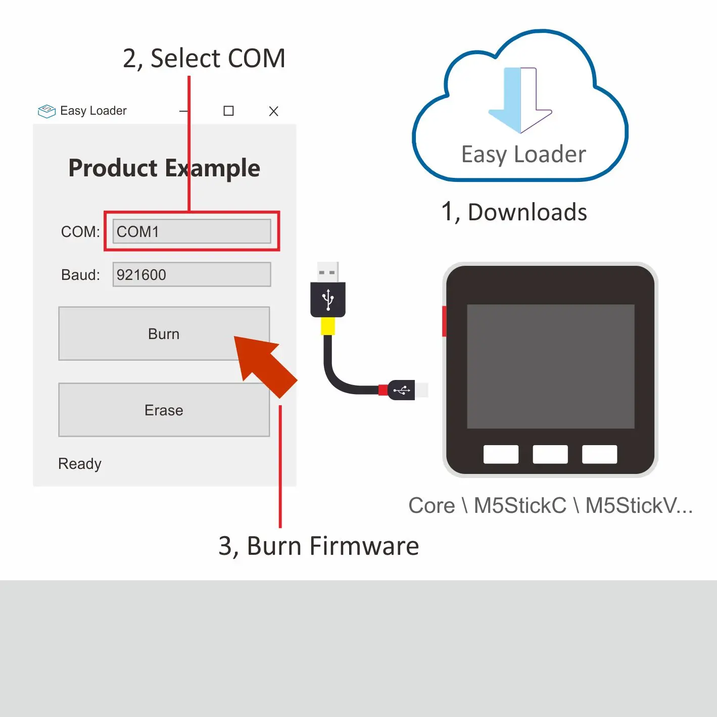
Description:
This case will perform hardware running tests for speakers, wifi, buttons, accelerometer, TF-card(microSD), screen, etc.
PinMap
LCD & TF card
LCD :320x240 TF card Maximum size 16GB
| ESP32 Chip | GPIO38 | GPIO23 | GPIO18 | GPIO5 | GPIO15 | |||
| AXP192 Chip | AXP_IO4 | AXP_DC3 | AXP_LDO2 | |||||
| ILI9342C | MISO | MOSI | SCK | CS | DC | RST | BL | PWR |
| ESP32 Chip | GPIO38 | GPIO23 | GPIO18 | GPIO4 |
| TF Card | MISO | MOSI | SCK | CS |
CAP.TOUCH
| ESP32 chip | GPIO21 | GPIO22 | GPIO39 | |
| AXP192 | AXP_IO4 | |||
| FT6336U | SDA | SCL | INT | RST |
Mic & NS4168(Speaker)
| ESP32 Chip | GPIO12 | GPIO0 | GPIO2 | AXP_IO2 | GPIO34 |
| NS4168 | BCLK | LRCK | DATA | SPK_EN | |
| Mic | CLK | DATA |
AXP Power Indicator Light
| AXP192 | AXP_IO1 | AXP_LDO3 |
| Green LED | Vcc | |
| Vibration motor | Vcc |
RTC
| ESP32 Chip | GPIO21 | GPIO22 | |
| AXP192 | AXP_PWR | ||
| BM8563 | SDA | SCL | INT |
IMU(3-axis gyroscope & 3-axis accelerometer)
| ESP32 Chip | GPIO21 | GPIO22 |
| MPU6886 | SDA | SCL |
USB to serial chip
| ESP32 Chip | GPIO1 | GPIO3 |
| CP2104 | RXD | TXD |
Internal I2C connection
| ESP32 Chip | GPIO21 | GPIO22 |
| MPU6886 | SDA | SCL |
| AXP192 | SDA | SCL |
| BM8563 | SDA | SCL |
| FT6336U | SDA | SCL |
Charging current measured value
| charging current | Fully charged current(Power OFF) | Fully charged current(Power ON) |
| 0.219A | 0.055A | 0.147A |
M5Core2 M-BUS Schematic diagram

M5PORT EXPLAIN
| PORT | PIN | Note: |
|---|---|---|
| PORT-A(Red) | G32/33 | I2C |
ESP32 ADC/DAC
| ADC1 | ADC2 | DAC1 | DAC2 |
|---|---|---|---|
| 8 channels | 10 channels | 2 channels | 2 channels |
| G32-39 | G0/2/4/12-15/25-27 | G25 | G26 |
For more information about Pin assignment and Pin Remapping, Please refer to ESP32 Datasheet
Related Link
-
Datasheet
-
API
Schematic


Example
1. Arduino
- Clickhere to get Arduino code